Architecture
Diagram
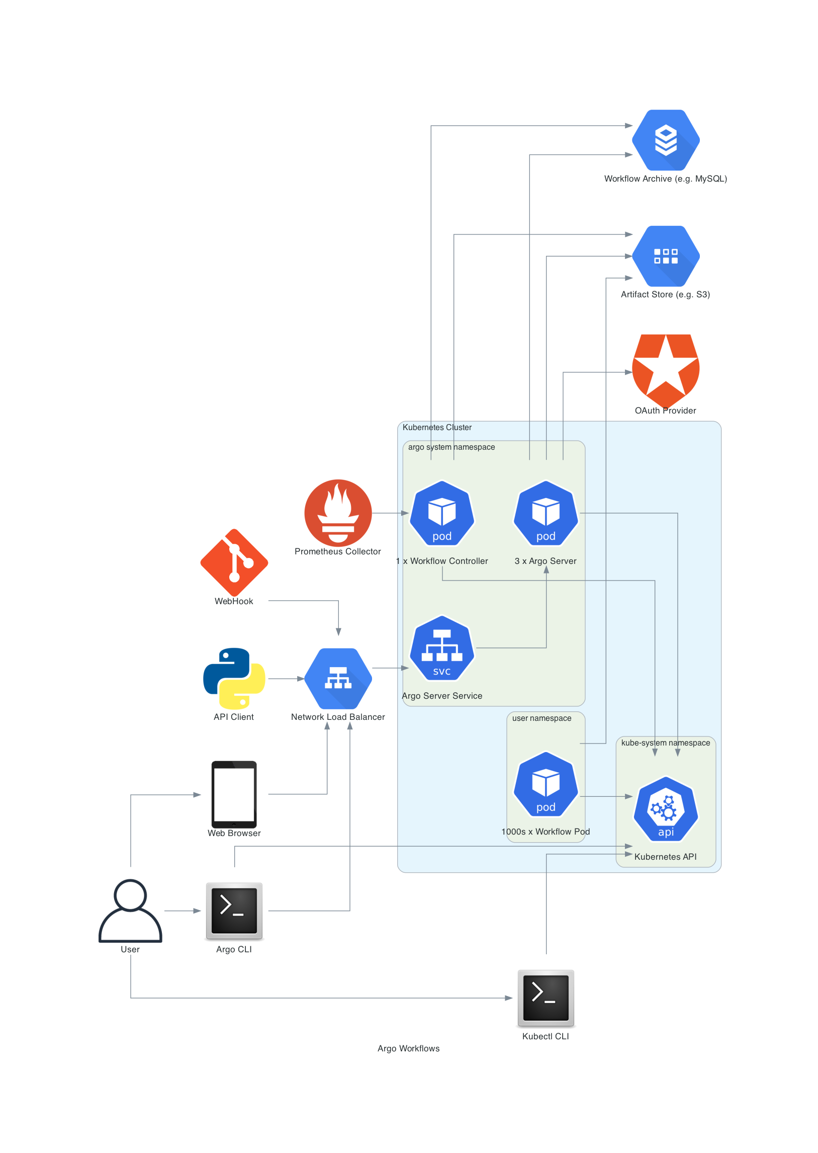
The following diagram shows the components of the Argo Workflows architecture. There are two Deployments: Workflow Controller and Argo Server. The former does all of the reconciling, and the latter serves the API. Note that the Controller can be used stand alone.
The reconciliation code for the WorkflowController can be found in workflow/controller/controller.go. The Argo Server opens up an HTTP(S) listener at server/apiserver/argoserver.go.
Argo Workflow Overview
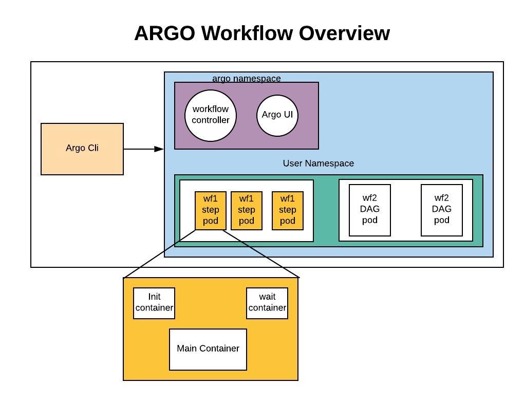
The diagram below provides a little more detail as far as namespaces. The Workflow Controller and Argo Server both run in the argo namespace. Assuming Argo Workflows was installed as a Cluster Install or as a Managed Namespace Install (described here), the Workflows and the Pods generated from them run in a separate namespace.
The internals of a Pod are also shown. Each Step and each DAG Task cause a Pod to be generated, and each of these is composed of 3 containers:
maincontainer runs the Image that the user indicated, where theargoexecutility is volume mounted and serves as the main command which calls the configured Command as a sub-processinitcontainer is anInitContainer, fetching artifacts and parameters and making them available to themaincontainerwaitcontainer performs tasks that are needed for clean up, including saving off parameters and artifacts
Look in cmd/argoexec for this code.
Init-less pod layout (opt-in, beta)
When the controller is configured with initlessPod.enabled: true, workflow pods use an alternate two-container layout with zero init containers. The argoexec binary is delivered into main via a Kubernetes image volume (KEP-4639 — Beta in 1.33 behind a feature gate, GA in 1.36), and a new supervisor container takes over both the pre-main responsibilities of the legacy init container (template write, script staging, input artifact download) and the post-main responsibilities of the legacy wait container (observe main, capture outputs, save artifacts and logs). Artifact plugins run as regular sidecars rather than as init containers, and supervisor drives each sidecar for both Load (pre-main) and Save (post-main). See Init-less Pod Layout for details.
Workflow controller architecture
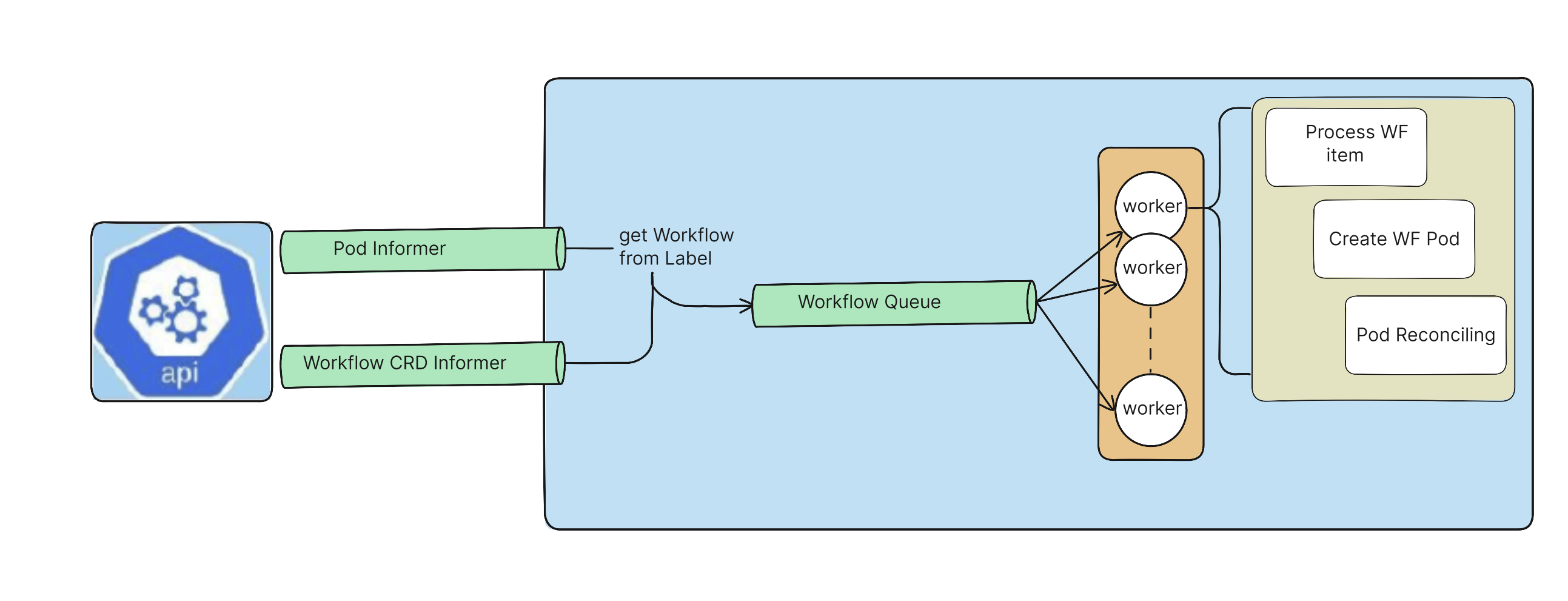
The following diagram shows the process for reconciliation, whereby a set of worker goroutines process the Workflows which have been added to a Workflow queue based on adds and updates to Workflows and Workflow Pods. Note that in addition to the Informers shown, there are Informers for the other CRDs that Argo Workflows uses as well. You can find this code in workflow/controller/controller.go. Note that the controller only ever processes a single Workflow at a time.
Various configurations for Argo UI and Argo Server
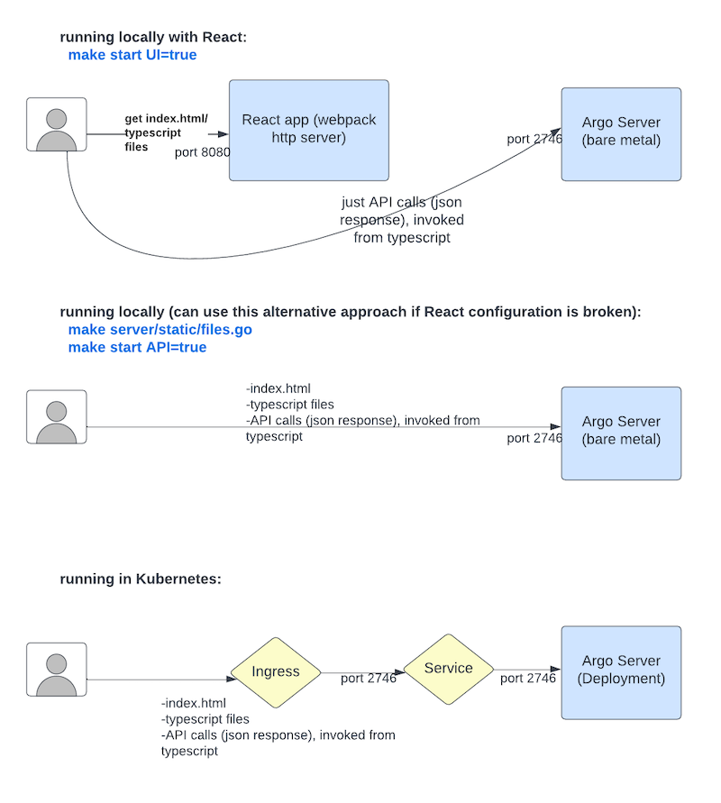
The top diagram below shows what happens when you run "make start" locally. This runs a React application (Webpack HTTP server) locally which serves the index.html and typescript files from port 8080. From the typescript code there are calls made to the back end API (Argo Server) at port 2746. The Webpack HTTP server is configured for hot reload, meaning the UI will update automatically based on local code changes.
The second diagram is an alternative approach for rare occasions that the React files are broken and you're doing local development. In this case, everything is served from the Argo Server at port 2746.
The third diagram shows how things are configured for a Kubernetes environment. It is similar to the second diagram in that the Argo Server hosts everything for the UI.